|
Polarization Evolution |
|||||||||||||||||
|
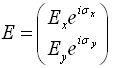
Description: The Jones vector, developed by R. C. Jones in 1941, represents efficiently the polarization state of a plane wave. A Jones vector is given:
It contains complete information about the amplitudes and the phases. When an optical system, such as polarization scrambling, consists of several optical elements oriented at different azimuth angles, the calculation of the overall transmission becomes complicated and is greatly facilitated by a symmetric approach. The Jones calculus is a powerful 2X2 matrix formulation. In this method each optical element is represented by a 2X2 matrix. The overall matrix for the whole system is obtained by multiplying all the matrices, and the output beam polarization state is achieved by multiplying the overall mall matrix and input beam Jones vector. Moreover, the polarization state evolution is able to be visualized on Poincare sphere surface. Features:
Example 1: Polarization Scrambling
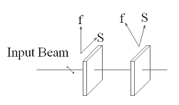
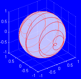
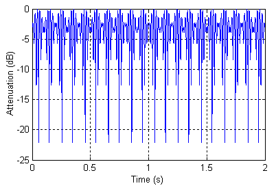
Polarization is a fundamental property of light. It is an important factor in an optical system design, such as polarization related impairments in a high bit rate optical communication system induced by the polarization mode dispersion (PMD). Variable wave plates are able to be used to analysis the polarization or scramble it to mitigate the impairments. Figure 1 shows a polarization scrambling configuration by two variable wave plates orientated at a 45 azimuth with each other. The variable wave plates could be LiNbO3 by using electro-optical effect or liquid crystal. Each wave pate has a maximum 2π phase retardation. The second wave plate is modulated 10 times faster than the first waveplate and has a maximum 2π phase retardation every 0.1 second. The initial polarization is a linear polarization which has 45° with respect to slow axis of the first wave plate. Figure 2 shows the polarization evolution on Poincare sphere surface. If a polarizer is placed after the second wave plate and aligned with slow axis of the first wave plate, the output intensity is modulated periodically and figure 3 shows attenuation verse time curve.
Bibliography: [1] Amnon Yariv and Pochi Yeh, “Optical Waves in Crystals”, John Wiley & sons Inc. (2003) [2] Christopher C. Davis, “Lasers and Electro-Optics”, Cambridge University Press. (1996) |
||||||||||||||||||

Copyright © 2016 Precision Micro-Optics Inc. All Rights Reserved.