|
Optical Field Propagation |
|||||||||||||||||
|
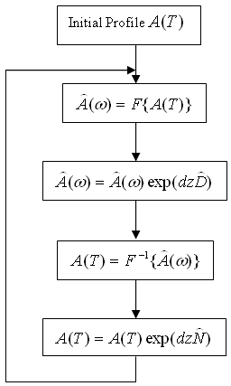
Description: Like all electromagnetic phenomena, the propagation of optical fields in a linear/nonlinear, dispersive/nondispersive, homogeneous/inhomogeneous or isotropic/anisotropic media in a guided/unguided structure is governed by Maxwell’s equations. It includes a wide spectrum. For each specific case, a basic equation is obtained such as the nonlinear Schrodinger equation (NSL) for pulse propagation in a waveguide, or the paraxial Helmholtz Equation for beam propagation in free space. The equations usually are nonlinear partial differential equations that do not have analytical solutions except for some specific cases. A numerical approach is often necessary to understand the nonlinear, dispersion and other effects. Taking the pulse propagation in a waveguide as an example, one widely used method to solve NSL equation is the split-step Fourier method. The split-step Fourier method assumes that the dispersion and nonlinear effects can be pretended to act independently over a small distance dz. More specifically, pulse propagation form z to z+dz is carried out in two steps. The nonlinearity acts alone in the first step while the dispersive effect act alone in the second step indicated in figure 1 flow diagram.
Features:
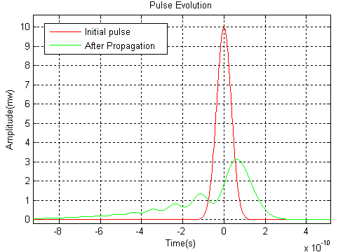
Example 1: Third-order Dispersion Effect
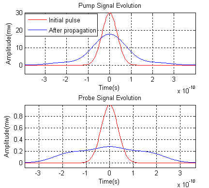
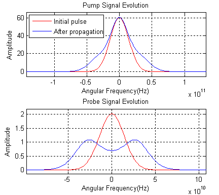
Example 2: Cross-phase Modulation
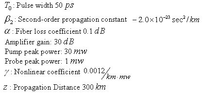
Figure 3 shows both pump and probe pulses’ evolution and assumes both pulses have same polarization. The probe pulse experiences a much bigger broadening in both time and frequency domains induced by cross-phase modulation. Bibliography: [1] Govind P. Agrawal, “Nonlinear Fiber Optics”, Academic Press (1995) [2] Hohn M. Jarem and Partha P. Banerjee, “Computational Methods for Electromagnetic and Optical System”, Marcel Dekker Inc. (2000) [3] Bahaa E.A. Saleh and Malvin Carl Teich, “Fundamentals of Photonics”, John Wiley & Sons Inc. (1991) |
||||||||||||||||||
Copyright © 2016 Precision Micro-Optics Inc. All Rights Reserved.

 Services
